Beskrivelse
Features
1、8 Bit MCU Chip: The ESP8266 WIFI relay module uses ESP‑01 as the WIFI module, with a mature and stable 8 bit MCU chip
2、Simple Configuration Process: Only a simple configuration process can realize the wireless control of the relay in the local area network using the mobile phone APP, onboard mode selection and real time working status indicator
3、100meter Maximum Transmission: The maximum stable transmission distance is up to 100meter when the mobile phone is mounted on the WIFI module in an open environment
4、Power Off Memory: Use for Smartconfig technology to complete the configuration of the account and password of the ESP‑01 WIFI module on the mobile phone APP, and the configured account and password have the power off memory function
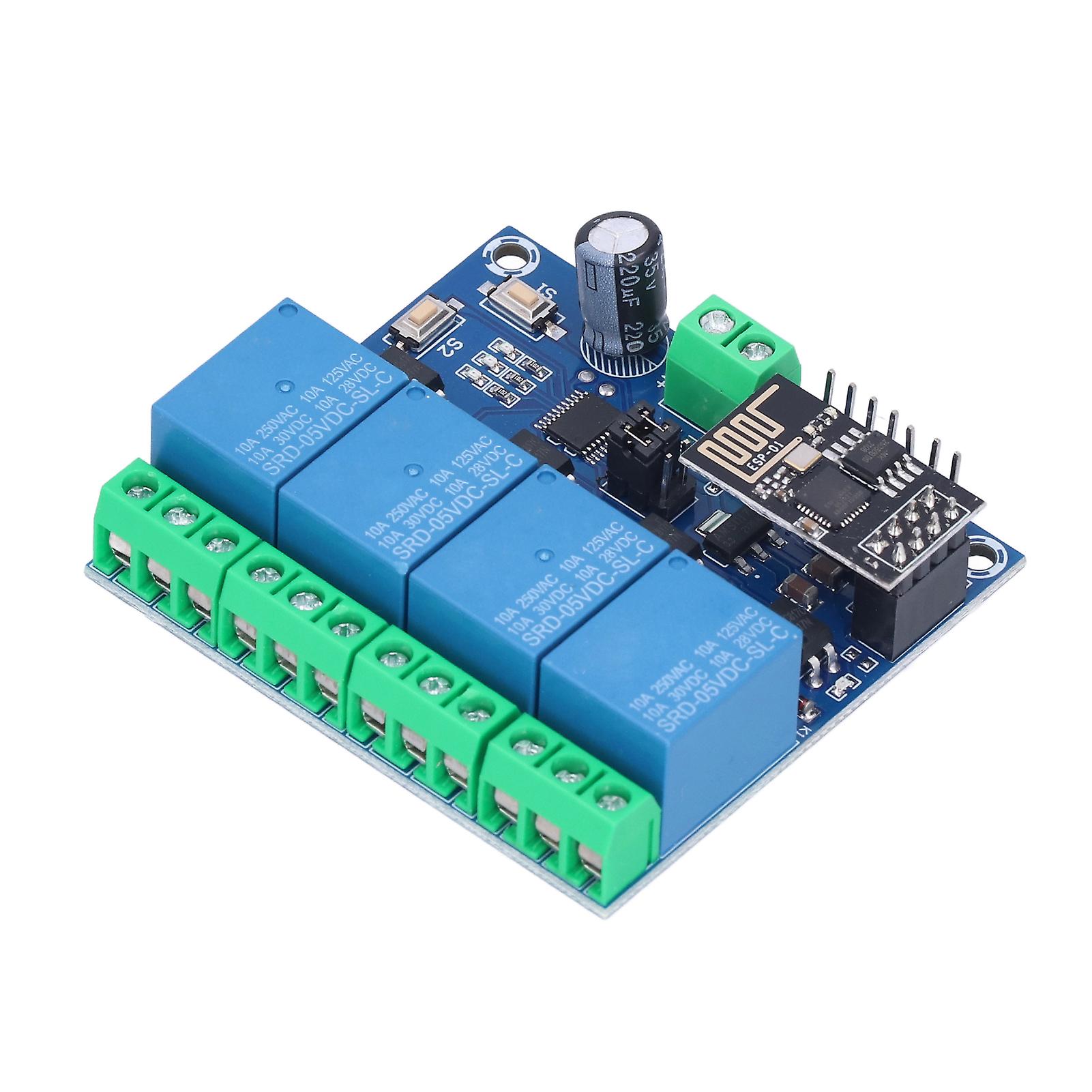
5、Short Response Time: Onboard 10A/250V AC, 10A/30V DC relay, can be activated continuously for 100,000 times, with diode effusion protection, bring short response time
Specification
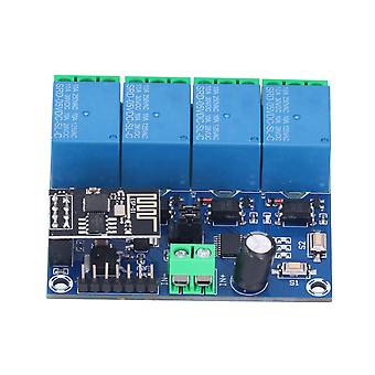
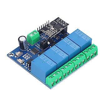
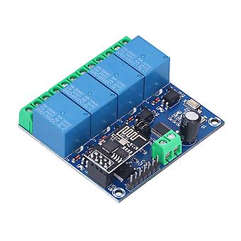
Item Type: WiFi Relay Module
Onboard: High performance microprocessor and ESP-01WIFI module
2 Working Modes:
The mobile phone is directly mounted on the WIFl module; the mobile phone and the WIFI module are both mounted on the router
Additional Function: Can be used as a USB relay when ESP-01 is unplugged
Transmission Distance:
The Maximum Stable Transmission Distance: Approx. 100meter / 328.1ft
When the WIFI module and mobile phone are mounted on the router at the same time, the transmission distance depends on the signal strength of the router
Reserved: UART debugging interface and MCU program download interface
How to Use:
IN+, IN-: Power input.
GND, TX, RX: UART serial port pins.
SWIM, PIN8, NRST: Reserved MCU program download port.
Button S1: Mode switching, the default is mode 1.
Button S2: Restore factory settings.
LED D1/D2/D3/D4 (red light): Relay working indicator light, lights up when it is turned on.
LED D7 (red light): Mode 1 indicator light.
LED D5 (blue light): Mode 2 indicator light.
LED D6 (green light): Working Status Indicator, Described As Follows:
(1) When it is off, it means it is self configuring or loses connection with the router.
(2) When 0.5S flashes quickly, it means waiting for the mobile APP to configure the WIFI account and password for the ESP-01 module.
(3) When the 2S flashes slowly, it means the configuration is completed, and it is waiting to establish a TCP connection with the mobile phone.
(4) When it is always on, it means that the TCP connection is successfully established with the mobile phone.
The Two Reserved Jumper Caps: Please insert them to the bottom in normal use (ie RX connects to RX1, TX connects to TX1), if you want to use the USB to TTL serial port module to debug the ESP-01 module, please insert them to the top ( Otherwise there may be interference).
COM1: Common terminal.
NC1: Normally closed, the relay is short connected with COM1 before it is switched on, and it is suspended after it is switched on.
NO1: Normally open terminal, the relay is suspended before the pull in, and short circuited with COM1 after the pull in.
COM2: Common terminal.
NC2: Normally closed, the relay is short connected with COM2 before it is closed, and it is suspended after it is closed.
NO2: Normally open terminal, the relay is suspended before the pull in, and short circuited with COM2 after the pull in.
COM3: Common.
NC3: Normally closed, the relay is short connected with COM3 before it is switched on, and it is suspended after it is switched on.
NO3: Normally open end, the relay is suspended before the pull in, and short circuited with COM3 after the pull in.
COM4: Common terminal.
NC4: Normally closed, the relay is short connected with COM4 before it is closed, and it is suspended after it is closed.
N04: Normally open end, the relay is suspended before being closed, and shorted to COM4 after being closed.
Relay Control Command (hexadecimal hex format):
Turn On The First Relay: A0 01 01 A2
Close The First Relay: A0 01 00 A1
Open The Second Relay: A0 02 01 A3
Close The Second Relay: A0 02 00 A2
Open The Third Relay: A0 03 01 A4
Close The Third Relay: A0 03 00 A3
Turn On The Fourth Relay: A0 04 01 A5
Close The Fourth Relay: A0 04 00 A4
Package List
1 x WiFi Relay Module
-
Fruugo-ID:
339966448-745757799
-
EAN:
6117160008631
Produktsikkerhetsinformasjon
Vennligst se produktsikkerhetsinformasjonen som er spesifikk for dette produktet skissert nedenfor
Følgende informasjon er gitt av den uavhengige tredjepartsforhandleren som selger dette produktet.
Produktsikkerhetsetiketter

Sikkerhetsadvarsler:
Please do not allow your child to handle this product alone to avoid swallowing or other injuries; adult supervision is recommended.